Making Use Of Limiters and Compressors
ARE YOU interested in improviiing your market coverage, perhaps at low cost? Are levels of your TV film features either too loud or too soft? Are line feed levels apt to be most unpredictable? Do you still get some of those complaints about loud commercials? Do you know the main differences between compressors and peak limiters, and how to use them to best advantage? There are undisputably many useful applications for audio compression, but there is also a great deal of confusion. To learn how audio compressors and limiters can be best applied to your own operations, read on.
Limiters vs. Compressors
Certainly in any discussion of
this sort, the first consideration
is to point up the basic differences between compressors and
limiters. This one area has been
the cause for many cases of misapplication, to the detriment of
the broadcast signal, with accompanying disappointment to both engineering and management. In
Fig. 1 Curve A illustrates a linear
input/output relationship, or no
compression, whereas Curve C
shows the shelving-type compression achieved with typical peak
limiting devices. While the compression ratio shown is 10:1,
which means that for a 10 db increase in _input signal the output
increases but 1 db, compression
ratios of 30:1 are not unusual
for peak limiters.
Peak limiters offer a very fast
attack time, typically on the order
of a few hundred microseconds,
some even faster. Abrupt loud
program passages and steep wavefront transients of high amplitude will be caught quite effectively by the peak limiter, and
held to a level which, while perhaps briefly audible, does prevent
overmodulation and splatter.
Thus, there is no doubt about the
value of the peak limiter at the
transmitter site.
However, the use of such a fastattack, severely-shelved compression characteristic, as a method
for increasing modulation density, would be highly objectionable
to the listener. The dynamic volume range of music would sound
squelched to an unnatural degree.
A brass or tympani forte would
be completely frustrated by the
shelving action of the limiter
curve.
Curve B of Fig. 1 illustrates
a compression curve which, from
a listening standpoint, is much
less objectionable than Curve C.
Note that the knee is less abrupt,
and the compression ratio of 3:1
is more gentle in action. As a
matter of practical fact, 20 db or
more of compression of this type
can be used without the listener
being aware that considerable
compression is in use. Moreover,
average modulation level would
be increased considerably, with an
accompanying increase in effective radiated power on AM and
in apparent loudness on FM.
The shape of the compression
curve is most important in differentiating a compressor from
a peak limiter. To impose the
shelved curve on your studio program levels would be onerous; to
apply the more gentle compression
curve as a means for catching
the troublesome program peaks
which cause overmodulation would
be inadequate. Let us continue a
bit further in this vein.t further in this vein.
There is another aspect of compressors and peak limiters which
is quite important, and this is the
release time, or the finite time it
takes for the device to recover
from a considerable degree of
compression. If the device recovers too rapidly, the abrupt upand-down variations in program
level produce the familiar "pumping effect," quite objectionable
to the ear. When coupled with a
fast attack time and adjusted for
plenty of compression, a slow release time will chop distinct holes
in the audio if triggered by severe
level changes such as pistol shots,
audience reaction, or an excited
announcer. The recovery time of
either a peak limiter or a compressor should be adjusted to the
nature of the program. But remember that despite fancy names,
the recovery circuit is basically a
capacitor discharge curve, and the
charging voltage is a direct function of program level and degree
of compression used. While this
obviously offers some degree of
program-controlled recovery, there
is no optimum release time setting for all program types.
Transmitter Applications
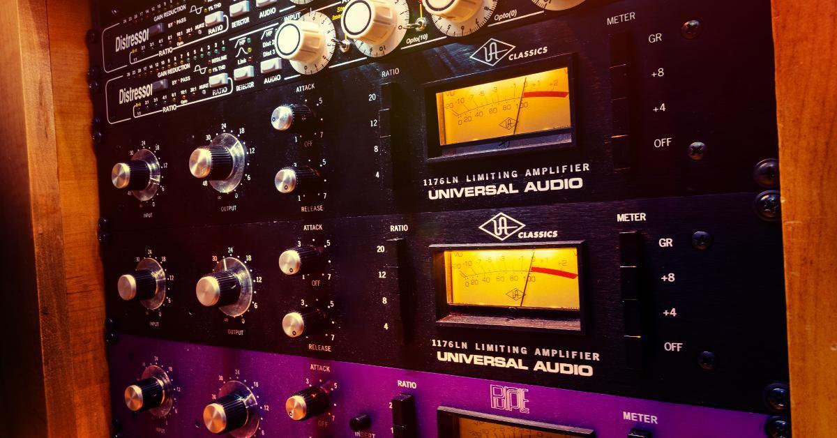
Most of the peak limiters currently available, or in current use,
are listed in the accompanying chart. These units are all designed for rack mounting at the transmitter. The two solid-state designs use quite sophisticated circuitry for at least two logical
reasons. The first involves elimination of conventional audio rectification to control the gain of
a variable-mu tube. There are no
variable-mu transistors as yet!
The second is based upon other
advances in circuit technology offered by semiconductors.All of the units except one provide considerable gain, which
must be taken into account. The
studio line is delivering +8 dbm,
and the transmitter audio circuits
require nominally about zero dbm
for full modulation. Therefore,
much of the gain supplied by the
peak limiter must be dumped, or
it will adversely affect signal/
noise ratio and overall distortion.
Because physical size is not a very
significant factor in rack-mounted gear, the choice of tube-type
or solid-state design is a matter
of weighing circuit features and
convenience controls vs. price.
While we are all familiar with
the reliability of well-made tube
equipment, solid-state devices have
a definite edge in freedom from
annoying maintenance problems,
and their stated characteristics do
not change as easily as tube
equipment.
Only two of the listed units are
supplied for FM stereo in one integrated package. Where two independent units must be purchased, they must be connected
so that the degree of compression
and the time constants are identical. Otherwise, the stereo effect
will be degraded.
Compressor Amplifiers
Of the various compressors
listed in the chart, all but two
include an amplifier in the package. Thus, in addition to method
of mounting and power supply requirements, you must also consider how to cope with the amplifier gain. Two of the peak
limiters listed also appear in the
compressor section. They are optionally designed to do a dual
job, accomplished by adjusting
the several controls as directed
in the instruction manuals.
Several of the units are designed for rack mounting and
are self-powered from a 117v
source. If they are wired to follow the usual console output, gain
must be dumped, except to make
up for compression losses. The
maximum output capability of a
few is borderline if used in place
of the regular console program
amplifier.
Some of the compressor units
are designed for plug-in console
or rack-shelf mounting, and require an external power source,
such as the console supply. Obviously, these units can be readily
substituted for the console program amplifier with little problem. If they do not already match
the mounting system of the console amplifiers, it is not difficult
to accommodate them within the
confines of the console shell. Their
gain and input level requirements
have been made compatible for
direct substitution with regular
program amplifiers, and they do
an adequate job of compression
at reasonably low cost. Unfortunately, these units do not lend
themselves to stereo use, as they
are not normally supplied with
a means for ganging compression
and time constant characteristics.
If identical but isolated units
are placed in each stereo program
channel, the one which is driven
hardest by a program peak will
compress more than the other
(and will take longer to recover).
This tends to degrade the stereo
effect at the listening end.
%2C_EMI_Presence_Box_(1960s)%2C_Altec_RS124_compressor_(1960s)%2C_Abbey_Road_Studios.jpg)
LDR Compression Devices
It is difficult to state the case
for the new LDR (light-dependent resistor) compressors without
sounding prejudiced in their favor. They have many practical advantages over more conventional
compressor amplifiers, and only
one significant disadvantage. An
LDR is a type of cadmium sulfide or cadmium selenide photocell that greatly varies in resistance depending upon the amount
of light which reaches it. This
simple component therefore lends
itself admirably to applications
for controlling gain in an amplifier or in a system. It is easily
adapted for remote control.
The LDR cell, if properly manufactured, contributes no noise to
the circuit in which it is inserted,
assuming that its net output level
after compression is not so low as
to be below the system input
noise. Distortion is a function of
the nonlinear resistance characteristics of the cells. Typical measurements show 0.55- THD or less
at +4 dbm output after 20 db
of compression. The distortion is
below 0.1%THD when the LDR is
inserted at typical internal system points, such as those shown
in the block diagram of Fig. 2.
Insertion loss is no more than 3
db when looking into a 600-ohm
load, and less than 1 db when
looking into the non-loading input
of some amplifiers.
The single fault with LDR's
lies primarily in the light source.
An incandescent light has a very
definite thermal characteristic
which delays activation of the
cell. This means that for compression (gain reduction) use it must
be classed as a slow-attack device when driven by a conventional lamp. If the lamp is powered
by AC, ripple voltages will be superimposed on the audio circuit
which the LDR is controlling.
Of course, the answer to thermal delay caused by the lamp is
to use an electroluminescent
source, and this has been done
successfully in the Teletronix
Model LA-2A. This rack-mounted
unit utilizes an LDR ahead of a
conventional amplifier, and although it is available adapted for stereo, its gain must be taken into account as mentioned earlier.
Although called a leveling amplifier, this unit can also be used
as a peak compressor because of
its fast attack time.
Two other units, the Melcor
Model C-20 and the Fairchild
Model 663, offer unusual versatility if you consider adapting
them to existing systems or designing them into new systems.
Attack time of about 15 milliseconds is a function of their incandescent light sources. Because
these units have no gain to contend with and virtually no insertion loss, and also because they
are packaged for control panel
mounting, they are unusually easy
to incorporate into an existing
system.
Applications
in the block diagram of Fig. 2,
a typical portion of an FM stereo
mixing console is depicted. The
two LDR's (labelled Comp. 1 and
Comp. 2) are inserted between
the master gain controls and the
program amplifiers. System levels
are indicated, including 15 db of
gain reduction due to compression. The common light amplifier
is bridged off the output of the
program amplifiers through a resistance network to insure proper
stereo isolation; at the same time
it allows sufficient driving level
to accomplish compression.
As the two LDR's are included
in one compressor module (as
many as 4 are possible), each
channel will be compressed the
same amount, regardless of which
has the higher program level, and
the common light amplifier provides the same time constant and
controls. Because the threshold
adjustment is a panel control, we
can take advantage of a feature not normally available in many
other units. Without disturbing
the system levels existing at the
point of insertion, the threshold
can be adjusted so as to start
compressing below this level. If
we assume that we are only interested in compressing levels
above normal, there will be little
need to adjust for compression
loss.
The LDR compressors, as with
many others in the list, act upon
average program content rather
than peak program energy. They
may be set for some degree of
compression at all times. During
periods of prolonged levels which
fall below the compression
threshold, expansion back to normal system gain will take place,
depending on the setting of the
release time adjustment, a panel
control. However, background
noise will never be any higher
than normal system noise, as
there is no extra gain supplied.
Adjusting the units to deliver a
specified curve is simply a matter of strapping terminals or
changing a resistor. The stepfunction curve of D in Fig. 1 is
possible for those applications
where compression is wanted only
over a 6 db range, with return
thereafter to a linear gain characteristic.
By raising the gain of the announce mic channel and adjusting
the compression threshold appropriately, the program can be made
to fade down under the announcer
( sometimes called "ducking"). It
will automatically fade back up
again after he stops talking. The
fade-up time is set by means of
the release time control.